Component Identification
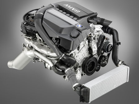
Engine
housing:-
· Engine block ( crankcase and bedplate )
·
Cylinder
head
·
Cylinder
head cover
·
Oil
pan
·
Gasket

Engine block :-
·
Made
from an aluminium die-casting
·
Consist
of the crankcase and bedplate.
Crankcase and bedplate :-
·
Crankcase
feature cast iron cylinder liners
·
Webs
between two cylinders on the deck on the block have a grooved cooling passage.
·
Coolant
flow along the grooves from one side of the crankcase to the other, thus
enhancing cooling of these area.
·
Five
oil return ducts on the exhaust side
·
Five
oil return ducts on the intake side

NO
|
EXPLAINATION
|
1
|
COOLING DUCT
|
2
|
CYLINDER
LINER
|
3
|
GROOVED
COOLING PASSAGE
|
4
|
OIL RETURN
DUCT, EXHAUST SIDE
|
5
|
OIL RETURN
DUCT, RETURN SIDE
|
Crankshaft :-
·
Lightweight
design, at 20.3 kg
·
Approximately
3 kg lighter than the crankshaft in N54 engine
·
Made
of cast iron ( GGG70 )
·
No
incremental wheel installed on the crankshaft
·
Counterweight
are arranged asymmetrically

NO.
|
EXPLAINATION
|
A
|
COUNTERWEIGHT
|
1
|
MAIN BEARING
JOURNAL 7
|
2
|
OIL HOLE FROM
BIG – END BEARING TO MAIN BEARING
|
3
|
OIL HOLE FROM
MAIN BEARING TO BIG - END BEARING
|
4
|
BIG – END
BEARING JOURNAL , CYLINDER 4
|
Pistons
and rings :-
·
A
full slipper skirt piston with a diameter of 82.5 mm.
·
1st
piston ring- plain rectangular compression ring with a chrome-ceramic coating
on the contact surface
·
2nd
piston ring- is a tapered faced Napier type ring
·
Oil
scrape ring- designed as a steel band ring with spring that is also known as VF
system

NO
|
EXPLAINATION
|
1
|
PLAIN
RECTANGULAR COMPRESSION RING
|
2
|
TAPERED FACED
NAPIER RING
|
3
|
VF SYSTEM
RING
|
4
|
STEEL INLAY
FOR FIRST PISTON RING
|
5
|
GROOVE FOR
FIRST PISTON RING
|
6
|
GROOVE FOR
SECOND PISTON RING
|
7
|
GROOVE FOR
OIL SCRAPER RING
|
8
|
HOLE FOR
LUBRICANT OIL DRAIN
|
9
|
GRAPHITE
COATING
|
Connecting
Road and Bearing :-
·
Size
– 144.35 mm
·
New
features is the specially formed hole in the small end of the connecting road.
·
This
formed hole is machined wider on the lower edges of the wrist pin bushing /
bore

NO
|
EXPLAINATION
|
1
|
BUSHING
|
2
|
CONNECTING
ROAD
|
Oil
pan :-
·
Made
up of aluminium casting
·
Oil
deflector and the intake pipe to the oil pump are designed as one component
·
To
facilitate attachment to the bedplate , the oil return ducts are designed so
that they extend over the oil deflector.

NO
|
EXPLAINATION
|
1
|
OIL PUMP
|
2
|
OIL RETURN
DUCTS , INTAKE SIDE
|
3
|
BEDPLATE
|
4
|
OIL DEFLECTOR
|
5
|
INTAKE
MANIFOLD WITH OIL SCREEN FILTER
|
6
|
OIL RETURN
DUCTS , EXHAUST SIDE
|